Hi!. I m working on a 2D packaging design. I m a new user of this program (Ipad), and I m trying to see if the UMAKE program fits well to work in this design direction (packaging). We are trying to figure out how to EXPORT a bi-dimensional file done in Umake (a carton-box design made with curves and lines- 2D ) to other editable-possible program and also the possibility to use a cutting program to get good results made with UMAKE. It looks like there are some options to EXPORT the files, BUT the people that are in charge to Edit the file created, can not EDIT anything of the drawing I sent, even they can not add some new line over the drawing to CUT the file in a cutting table. (It looks like it’s possible to open the file in SolidWorks, but the file is not editable x example)…They can not use the file to make samples over the cutting table either . Does it look like I need some assistance in that matter to know if it’s possible to use this program to work in 2 dimensions and cutting table(packaging)?. The question is to know which EXTENTION is the adécuate one? (Solid Work or CaseMake). I m also wondering if it is necessary to set up some settings in those programs mentioned in draw editing?. Appreciate the time and thank you for your possible assistance!. Et
Hi @ETR,
Thank you for the questions and hope all is well.
While uMake doesn’t have the option to “unfold” a 3D object into multiple 2D drawings/schemes, you can export the 3D model as IGES/STEP file which are neutral 3D file-formats and can be opened in SolidWorks.
Have you tried exporting to IGES/STEP? Which file format did you send them?
Thank you,
Evi
Hi Evi!
Thanks a lot for your quick reply!. Appreciate really your time. Thanks in advance!. I need that at that moment because if not, I need to change the program. It s crucial for me that the cutting department where I work could have the possibility to Edit (if it is necessary and cut the sample. I understand that the UMAKE program has not the potential to «unfold». I don’t need that, I think. I just need to send them an editable file format. I have sent them an IGES but they can see it on their screen, but the person that workshop there (she has not too much experience in that…)says that they could not work on the file to adapt some extra features!. It could be fantastic to have a cad format like DWG (because workshop in 2D). I just sent yesterday the IGES file with a vectorial-box design made in 2D. Do you think they could work on the STEP file if they open that one in Solid workshop??. This is the only option I have?. It s essential because if I can not communicate well with them correctly, I guess I need to find another program for that. If there is a setting in Solid works that you know well to open, please just let me know. Sorry to be little long in my explanation. I guess is the start… Appreciate your possible reply as soon as possible. KR. Et
(Attached is just a 10 % og the drawing).
Thank you for the explanation.
They should be able to import IGEs and STEp into SoldWorks:
You can try either:
- STEP - send them a version of the drawing in STEP file format
- IGES - try to change the end of the file from filename.iges to filename.igs, maybe that was the reason they couldn’t open it on their end.
As for DWG support - it’s on our roadmap and we would love to support it, it might take a bit of time.
Let me know if the suggested solutions work.
Thanks,
Evi
Hi Evi!
Thanks for your reply!
I really have not answer for your questions. Looks like its not possible.
I need people with more knowledge to lose this problem.
I just wonder and take this conclusion: If I need to send a bi-dimentions drawing made in Umake to other person thats works in SolidWorks (to make a drawing in 3D). This way…will not gonna work!.It is not possible to do it?. I means, or looks like, the only way to import a Umake file, must be 3D._-?. *and I m sure that this way will work well. Thanks. ETR
Thanks!
It doesn’t have to be in 3D, you can simply sketch a 2D drawing (for example, from a top view), export it to STEP or IGES and send it to your team members. They will be able to open it in Solidworks.
Let me know if this answers your question.
Thanks,
Evi
Hei Evi!. Thanks for your time again. I guess I have the wrong conclusions about that. It is also challenging to be physical with other ones because the Covid19 makes this issue more complicated. In a way, this is not something complicated. It is just to take the correct conclusion if it’s possible or not. For sure, I need to read more on the net and make contact with others that have the SolidWorks program!..I wonder if you have some other friends around you that can give us correct feedback related to this matter?. Appolagize to be long with my sentenses and explanation.Thanks again. ETR
@ETR Can you please send us an example/photo of what you would like to achieve? That way we can tell you if it’s something you can create in uMake and if it’s also something SolidWorks can open.
Thanks,
Evi
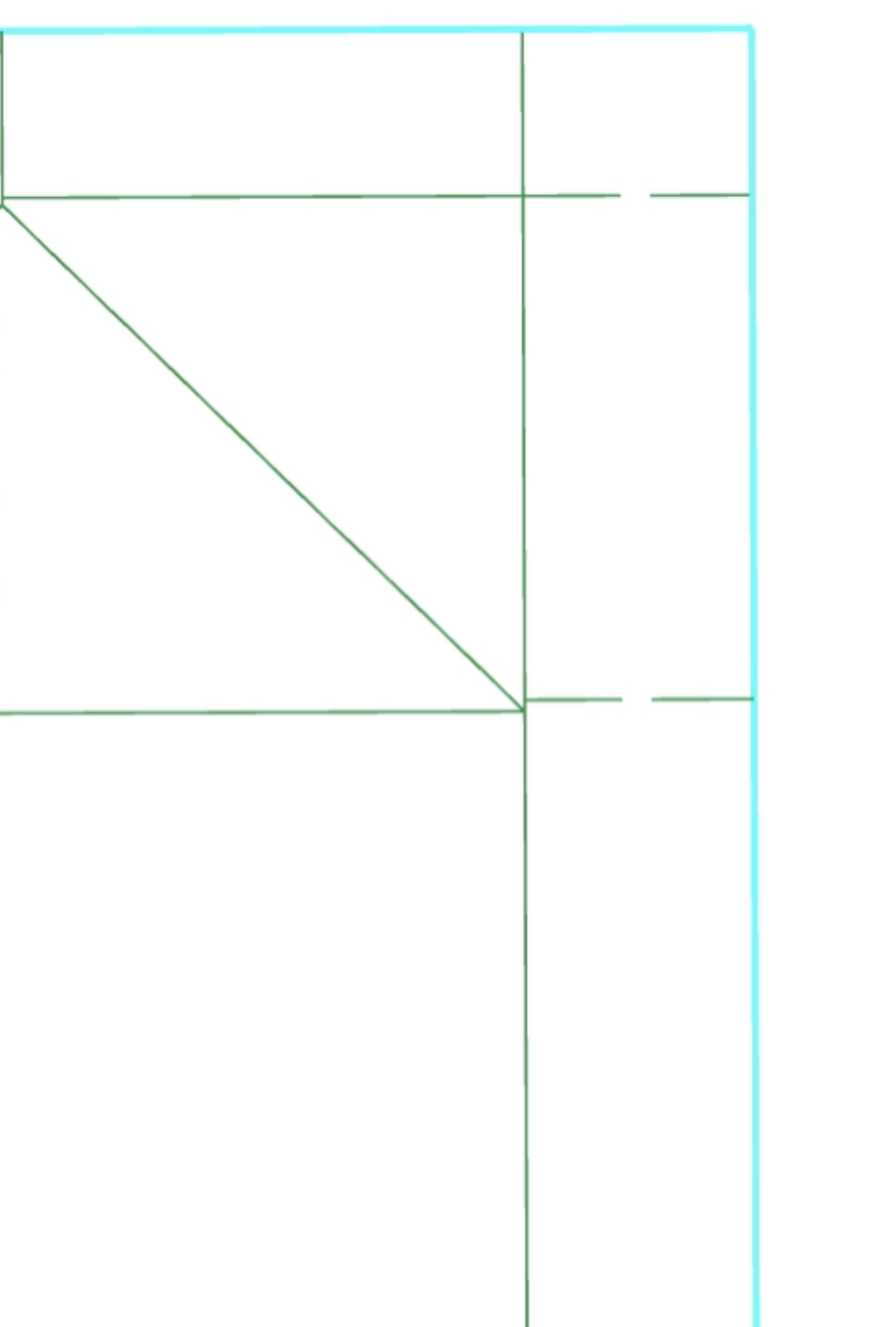
Hei Evi!. Thanks for yr reply! I m sending a part of my design. Like I mentioned before, this is just a 2D. vectorial drawing part of a packaging box. If you can open this file in SolidWorks and make it editable in solidworks, just let me know asap.(What I mean to be editable: if you kan move the vectors in solid works to make for example oter type of configuration. If you kan see the layers x example could be also fantastic. Please let me know if you got the files.
2D Umake drawing for SolidW-IGES.iges (9.5 KB)
2D UMAKE drawing for SolidW-STP.stp (31.3 KB)
Thanks, @ETR.
Here’s a screenshot of SolidWork after opening the file in IGES file format. For some reason, the STP file didn’t show anything in SolidWorks, although I’m not sure why. Better use IGES in this case:
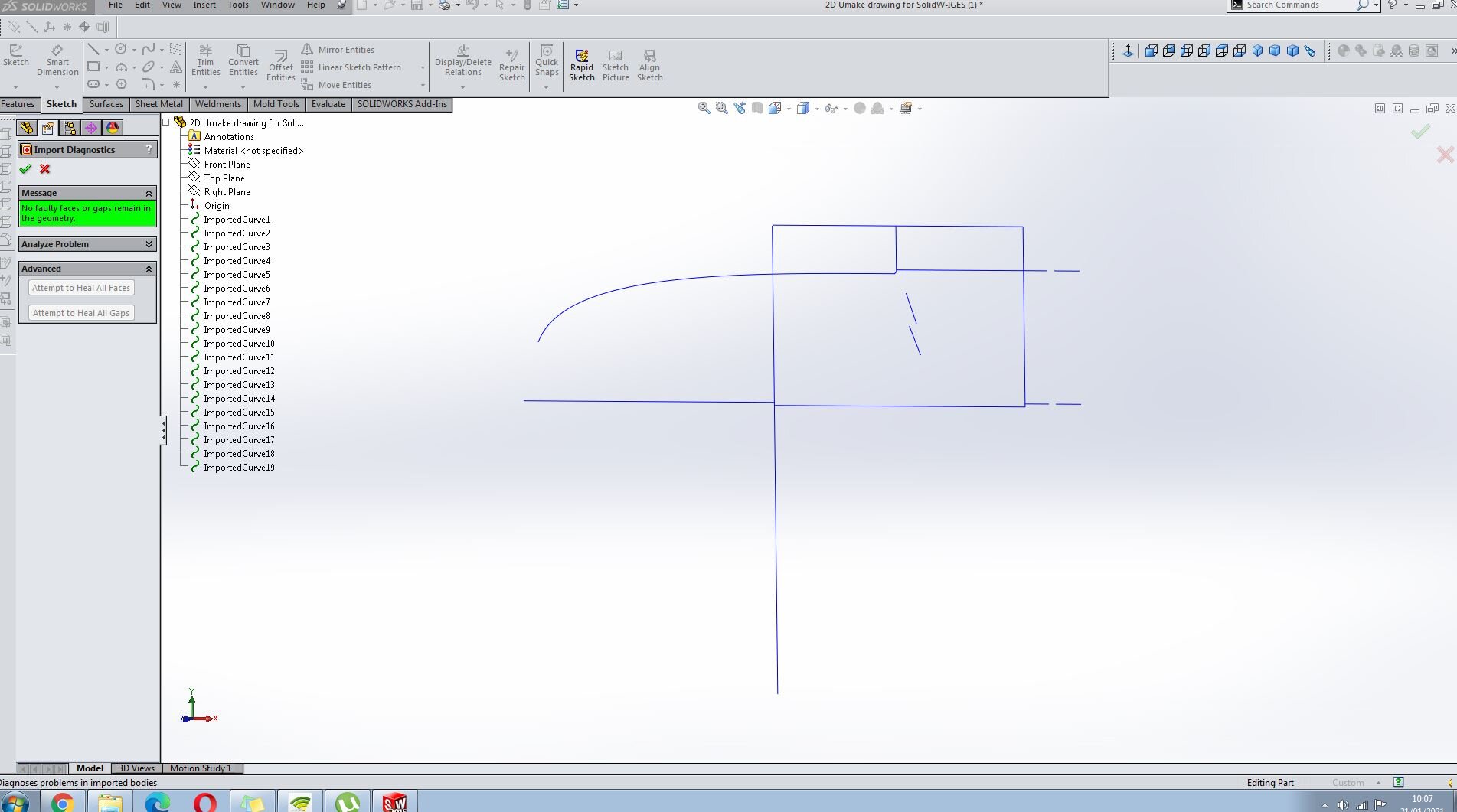
Was that what you were looking for?
Thanks,
Evi
Hei Evi!. Thanks. I know that it is possible to see it on the solidworks screen!. But let me know if its posible to use-edit the vectors you have there at the solidworks program??. If its posible to Edit them…try to add some extra drawing, and let me know it its possible to see the layers, What type of setting you have used!. Remember that I don t need to work in 3D. The people that works in solidworks need to send the file to the cutting table and finish the the problem. Thanks Et.
(If u dont mind. Let me know what is this square-black grid over the screen- The same square is on the files I have sent u before. I can not find the way to take it from the drawing place…?)
Sorry for the delay! Let me check it and get back to you asap,
Thanks,
Evi
@ETR,
Thank you for your patience.
After some testing we’ve made with SolidWorks, it seems that it’s not possible to edit these lines in SolidWorks. Not sure why this limitation on SolidWorks end, but I assume it’s because of the way it considered freeform/individual lines in a 3D space while managing a “solid space”.
Unfortunately, there isn’t something we can do on our end, besides supporting exporting to DWF/DWG, which SolidWorks able to properly read. We plan to add this support, but there’s no estimated date for it yet.
I understand it’s not the type of answer you expected to hear, but we hope we can resolve this issue in the near future.
Let me know if you have any questions.
Thanks,
Evi
Hi Evi!
Sorry for my late reply to your answer. Appreciate your reply and hope we could soon have a solution for that. I have started to do some modeling with the program, and for sure, I will come to you again!. Start to be interesting, and everything is new here for me. If you don’t mind, just when you have a gap in your time (related to the image attached), please let me know what is this square-grid that appears just on the middel of the drawing-plane?. How your manage to take it out from there?. Thanks. Esteban
Hi @ETR,
Hope the week started well for you!
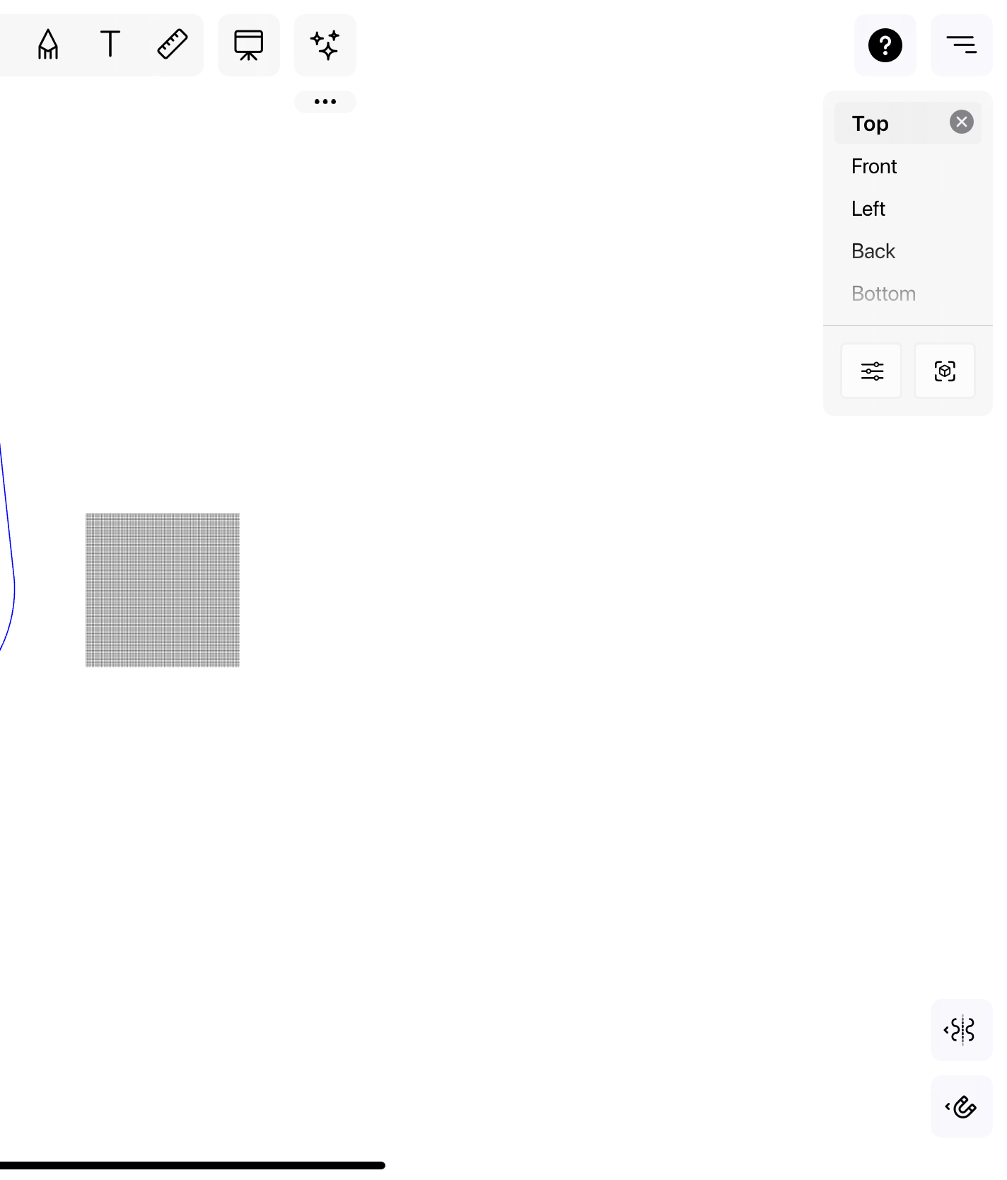
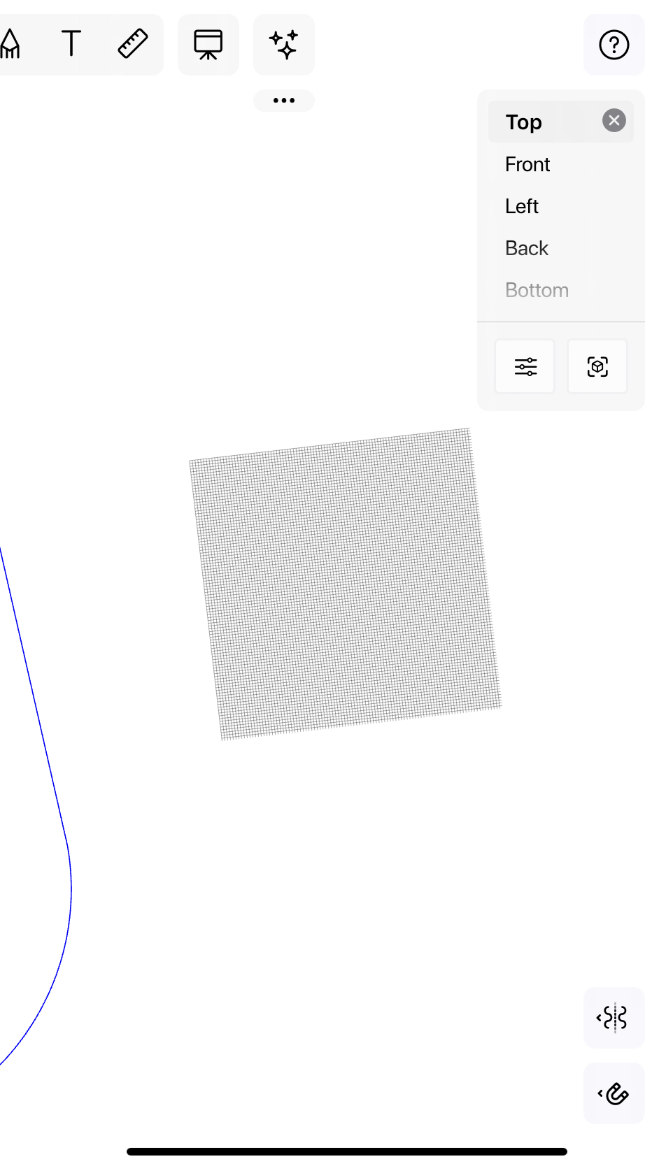
The rectangle is the grid of the 3D space. It looks like you configured the grid to be “Fixed”, which means that it won’t change based on the zoom level. So, for example, each rectangle in the grid is 1cm X 1cm, while with “Adaptive” grid it’s changing based on the zoom level (it can start with 10cm X 10cm then when zooming in it each rectangle can be 5cm X 5cm, then 1cm X 1cm).
If you want to change it back to “Adaptive”, open the views toolbar (where the “top”, front", etc. buttons are), tap on the “Settings” button, then tap on the “Grid” tab and change it back to “Adaptive”.
By the way, we just released a big update with many other user-experience changes, so if things look a bit different after you updated uMake - this is the reason.

Let me know if this helps.
Thanks,
Evi